Cool little tidbit worth reposting:
What Revit Wants: Insert a non-breaking space in Revit: A non-breaking space forces Revit to keep two words together, but there is still a visible white space between them. To do this, just hold...

Showing posts with label Revit Specific. Show all posts
Showing posts with label Revit Specific. Show all posts
Friday, November 11, 2011
Wednesday, January 19, 2011
Wall Function Trickery
As I was chugging away at my model today I came across a rather aggravating little trick within a wall's type properties. Maybe some of you know this already, maybe some don't but you learn something new everyday. Apparently within the wall's type properties, if your wall is set to a "Foundation" function you can't use a level above as the "Top Constraint."
Example: I can't have a 12" Concrete basement wall (with a "foundation" function) using the First Floor Level as a top constraint. You will get the "Top Constraint is invalid for the Level" error message, and boy is it aggravating! It must use the Basement Floor Level. Now I can offset it until my heart's desire but it can't associate with a level above.
Just a random factoid for the day!
Friday, November 12, 2010
Interactive Web-Based Model Viewing - Part Tres
After over a year of sitting idle, I had been fiddling with this app a bit more today. It should be working in the live now in the second post in this series. It uses one of the sample projects from RAC 2011 - Check it out.
Note:
If you are unable to see the model in the window - try signing out of blogger an viewing it as anonymous - I have had a little trouble viewing when I am signed in but it works like a charm when I am not.
Note:
If you are unable to see the model in the window - try signing out of blogger an viewing it as anonymous - I have had a little trouble viewing when I am signed in but it works like a charm when I am not.
Thursday, February 18, 2010
Interactive Web-Based Model Viewing - Part Duex
This is an elaboration of my post 'Interactive Web Based Model Viewing - Part Uno' - it looks at using the Autodesk Seek Viewer to view Revit models online - here is the original post.
It was a little tricky to get this to embed into my blog but I think I got it workable. By now, you should have already been prompted to run the Autodesk Seek Viewer add on and you should be able to see the model in the viewing window. If not, here is the direct link to the Autodesk Seek Viewer; just extract the .zip file and run the .exe file.
This example is using one of the sample projects from RAC 2011. As you can see this can be quite a valuable and lightweight tool. Right click in the viewing window somewhere and you can view the various settings and tools you have to play with - I especially like the Interactive Slicer.
Go ahead - have at it! It works very similiar to Revit as in panning, zooming, etc.
Split-Face with Wall Reveal
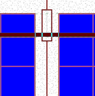
Have a complex wall/reveal design? Maybe EIFS reveals? Let's say you have a reveal in a wall and you need to have the portion of the wall above the reveal 'Color A' and below it 'Color B' - when you try and use your Paint Bucket it wants to select the entire face of the wall (Figure A), not the individual faces (above and below the reveal).
So the next logical step would be to use the Split-Face tool to split the wall face at the reveal location so you can have multpile faces to paint. After further investigation and frustration we see that when we select the wall face to split it, it automatically has the reveal edges assigned as a face border - so we can't split our faces along those lines. Now we could offset our split-face lines a teenie bit off the border lines but that would be cumbersome and annoying.
Well While going through this I discovered an long standing bug in the software, try this:
- Use your Split-Face tool and pick the wall face you would like to Paint.
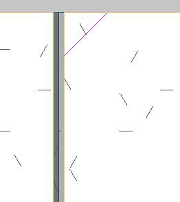
- Split the face of the wall anywhere, I do it in a top or bottom corner and create a tiny 1/16"x1/16" wedge (Figure B). Select Finish Sketch.
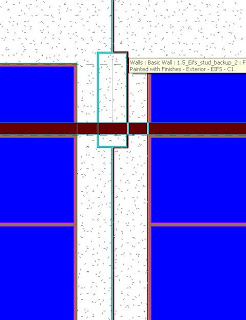
- Now you will be able to pick the individual faces of the wall created by the reveal (Figure C).
Thursday, February 11, 2010
Curb and Gutter Along Topo
Want to create a curb and gutter that actually follows your topo elevations? Tired of using complex slabs or sloped sweeps? Well here's an alternative way that creates a curb and gutter to follow the EXACT topography of your site plan! The only downside I have found to this method is that you need to be sure your topography is final (or darn close) and won't change at the areas of the curb and gutter - it can be a nightmare to change after the fact - you'll see why as you go through this tutorial.
Happy Curbing!

Happy Curbing!
- Create your toposurface as normal - making sure your elevations, etc are nailed down prior to moving on the the next step. :)
- Use the Split Surface tool to split the surface into 3 parts, forming your road - you'll have to do this twice as the Split Surface tool only allows you to split the surface into two parts each time.
- On each side of the road, use the Split Surface tool again to split the surface into (2) 6" (or whatever your specs) pieces or slivers outward from each side of your road - this will later become the top of your curb and your gutter.
- Go to an elevation view and move the road, and the two inside most 6" pieces (your gutters) down your required curb height.
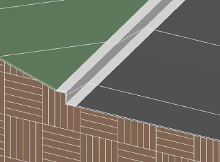
- Assign the appropriate materials to the roadway, curbs and topo (asphalt, concrete and grass) - now you can see things shaping up.
- Now, using the Split Surface tool again, Split each of the four 6" spaces 1/8" from the their shared edge - creating (2) 1/8" slivers of curb in between each of the two 6" pieces.
- Finally, go to a 3D view and use the Merge Surfaces tool and select the lower 1/8" curb piece and then the upper 1/8" curb piece - this will join the two 1/8" pieces to create your curb wall.
Thursday, August 13, 2009
Interactive Web-Based Model Viewing - Part Uno
You can use the Autodesk Seek Viewer plug-in as a viewer that is even lighter and easier to use than Design Review to view your Revit models (DWF versions) on the web:
1.) Once you have your Revit model published to a 3D DWF, go to the Autodesk Seek website and select a family to view 3D in the Autodesk Seek Viewer
2.) If you haven't been to the Autodesk Seek website before, download and install the plug-in - save the plug-in, you'll want it later.
3.) Once installed and viewing the family, right-click and selectcopy the source code to a blank notepad document.
4.) Sift through the code (there's not a whole lot to it) and replace the source location of the Autodesk Seek family with the location of your DWF. There are additional parameters for background color and gradient, initial camera view parameters such as pitch, roll, elevation and zoom factor you can play with.
5.) Save the file with the .html file extension
6.) Open the .html file in Internet Explorer and Voila! You now can view your Revit model in a simple, lightweight, easy to use viewer on the web with all the same amenities (render modes, interactive splicer, etc) as the Autodesk Seek website.
Anyone who has ever been to the Autodesk Seek website and installed the Autodesk Seek viewer plugin can view these right away; and what about the rest who have not? Well, you'll have to put a link on your website so they can install it on there machines; that's why I suggested to save the plug-in when downloading it from Autodesk. :D
This is a great tool for marketing a large multi-unit development where you could have an online Site Plan of the development and graphically link to an interactive 3D model of each unit. And it's simple enough that Joe-Shmo off the street can use it; a lot easier to use and less involved than Design Review.
1.) Once you have your Revit model published to a 3D DWF, go to the Autodesk Seek website and select a family to view 3D in the Autodesk Seek Viewer
2.) If you haven't been to the Autodesk Seek website before, download and install the plug-in - save the plug-in, you'll want it later.
3.) Once installed and viewing the family, right-click and select
4.) Sift through the code (there's not a whole lot to it) and replace the source location of the Autodesk Seek family with the location of your DWF. There are additional parameters for background color and gradient, initial camera view parameters such as pitch, roll, elevation and zoom factor you can play with.
5.) Save the file with the .html file extension
6.) Open the .html file in Internet Explorer and Voila! You now can view your Revit model in a simple, lightweight, easy to use viewer on the web with all the same amenities (render modes, interactive splicer, etc) as the Autodesk Seek website.
Anyone who has ever been to the Autodesk Seek website and installed the Autodesk Seek viewer plugin can view these right away; and what about the rest who have not? Well, you'll have to put a link on your website so they can install it on there machines; that's why I suggested to save the plug-in when downloading it from Autodesk. :D
This is a great tool for marketing a large multi-unit development where you could have an online Site Plan of the development and graphically link to an interactive 3D model of each unit. And it's simple enough that Joe-Shmo off the street can use it; a lot easier to use and less involved than Design Review.
Tuesday, June 16, 2009
Revit Implementation Checklist

1.0 o Program
2.0 o Develop Implementation Milestones and Schedule
3.0 o Core Team Selection
4.0 o Core Team Training
5.0 o Core Team Develops Office Project Template (Test Project)
5.1.0 o Non-template Related Items
5.1.1 o Export layer text file
5.1.2 o Import line weights text file
5.1.3 o Shared parameters file
5.2.0 o Line Weights
5.2.1.1 o Annotation line weights
5.2.1.2 o Model line weights
5.2.1.3 o Color delineations
5.2.1.4 o Revit grey scale vs. traditional acad screen
5.2.1.5 o Phasing
5.2.1.6 o Patterns
5.2.1.7.0 o Linked DWG Files
5.2.1.7.1 o Linked drawings files
5.2.1.7.2 o Linked with colors preserved vs. colors as black
5.2.2.0 o Plotters
5.2.2.1 o Large format, full size
5.2.2.2 o Large format, half size
5.2.2.3 o 11x17
5.2.2.4 o 8 1/2 x 11
5.2.2.5 o Document printer settings
5.2.2.6 o Adjust line weights and grey scale as needed based on plots
5.2.2.7 o Plot to PDF and DWF send to plotter (identify any issues)
5.2.3.0 o Print Setups
5.2.3.1 o Create print setups in office template for all applicable plot styles
5.3.0 o Tags5.3.1 o Create all office standard tags and load into office template
5.4.0 o Patterns
5.4.1 o Base set of patterns
5.4.2 o Office process for creating new patterns
5.5.0 o View Markers5.5.1 o Elevation markers
5.5.2 o Section (building, and wall section markers, if different)
5.5.3 o Detail bubbles
5.5.4 o Callouts
5.5.5 o Match line callouts
5.6.0 o Leader Arrows
5.6.1 o Text leaders
5.6.2 o Tag leaders arrows
5.7.0 o Dimension types
5.8.0 o Text
5.8.1 o Create types in the office template
5.8.2 o Create text types in the families
(detail components, generic annotations, all tag families, etc.)
5.9.0 o Schedules
5.9.1 o Create working schedules
5.9.2 o Create plotting schedules for all schedules
5.10.0 o Views and Sheets5.10.1 o Create typical levels
5.10.2 o Create standard views
5.10.3 o Create office title blocks (include all variety sizes used)
5.10.4 o Create typical sheets
5.11.0 o Family creation (in template or in library?)5.11.1 o Establish minimal set of working families
5.11.2 o Establish a routine for migration of families from project to office library (See 6.3)
5.11.3 o Determine which families are to be pre-loaded into template and which families are to be loaded as needed from the libraries
6.0 o Establish Office Revit Protocols (Test Project)6.1 o File structure for projects (i.e. correspondence, consultant files, and reference files; usually mimics traditional project file structures)
6.2 o Work sharing protocol
6.3 o Family creation, storage and protocols
6.4 o Family transition from project to office library
6.5 o System family protocols (walls, floors, roofs, etc.)
6.6 o Material and Plant Library protocol
6.7 o Keyboard shortcuts
6.8 o File support paths (paths to Revit standards file)
6.9 o Software upgrading
6.10 o Project phases
6.11 o Project archiving
7.0 o Revisit Item 1.0 - Program
8.0 o Pilot Project Selection
9.0 o Pilot Project Team and Training
10.0 o Pilot Project Development
11.0 o Revisit Item 7.0 - Program
12.0 o Train Rest of Office on Project by Project Basis
1.0 Program
Define the end product. What are we trying to accomplish with BIM? Record existing process flows through the office. Also, identify problematic areas where the software process may conflict with the office processes. At this time, a test project and a pilot project will be selected and the scopes and schedules of these projects will be determined.
2.0 Develop Implementation Milestones
Use outline above as a starting point; identify key areas/milestones that need to be achieved that can be measured quantitatively and qualitatively along with a schedule of estimated completion of each milestone.
3.0 Core Team Selection
This team will ultimately be responsible for the success of the implementation. This group will also be responsible for finalizing the office standards and implementation. This group should consist of a diverse staff base as possible to ensure different perspectives are seen (i.e. principles, project architects, drafting technicians, etc.).
4.0 Core Team Training
Formal software training of the Core Team.
5.0 Core Team Develops Office Project Template (Test Model)
Use the outline above (section 5) to begin sorting out and creating the project template. The project template should be created in conjunction with the test model.
Test Model
A set of typical drawings, small 15-20% reproduced in Revit. Include an area that has both interior and exterior walls, stairs, restrooms and roof area. Recreate each sheet that it appears in the final set of drawings.
This process will get the majority of the bugs out of the template and protocols before they are put into production as well as assist in developing the office template and protocols.
6.0 Establish Office Revit Protocols
The office Revit protocols and libraries should be created in conjunction with the test model (see section 5).
7.0 Revisit Item 1.0 - Program
Revisit the problematic areas identified in the initial programming phase and identify the solutions to these issues. Also, identify any new areas that need to be addressed. Re-evaluate and if necessary, redefine your “end product statement,” or what solutions can help to get back on track towards achieving our end result?
8.0 Pilot Project Selection
Select a project that will produce billable hours to be produced in the software as a pilot project.
9.0 Pilot Project Team and Training
This project can be produced by either the Core Team or a new Pilot Project Team.
Having the Core Team produce the pilot project allows for an already trained team to create a working model that can be used as an example in training future users.
Selecting a new Pilot Project Team allows for new users the get trained and familiarized with the software, the template and Revit office procedures on billable hours, but lacks an example model for them to reference and also can be subject to more billable hours due to the learning curve.
If elected, formal training will begin for the new Pilot Project Team. Also, they will be given basic training by the Core Team on the office template, libraries and protocols.
10.0 Pilot Project Development
Pilot project is developed to put the templates, libraries and protocols fully to the test.
11.0 Revisit Item 7.0 - Program
Another look must be given to the programming phase prior to moving into full production of Revit.
· Was my “end product statement” achieved?
· Were any issues that conflicted with current office procedures addressed and resolved?
If any issues have not yet been resolved, they should be addressed and dealt with before rolling out the software to the rest of the office. This is the time to deal with these issues so new users can focus solely on learning the software rather than dealing with loop holes in office protocols.
12.0 Train Rest of Office on Project by Project BasisNow formal software training can begin on other staff members. Treat the first project for each team as a pilot project. Give them basic training on the office template, and Revit protocols. Also, give them time to learn from the experiences gained by the pilot project/team and to share their views on what is working/not working with the office template, libraries and protocols.
Subscribe to:
Posts (Atom)